EE 210 Laboratory 04 Spring Semester
电子工程 This is the first of two laboratory sessions that introduces the op-amp. In this session, you will study three aspects of the op-amp···
This is the first of two laboratory sessions that introduces the op-amp. In this session, you will study three aspects of the op-amp: the open-loop saturation characteristics, the inverting amplifier transfer characteristic, and the non-inverting amplifier transfer characteristic. In the next laboratory session, you will study two other canonical amplifiers: the voltage follower/buffer and an inverting summing amplifier. You will also build a voltage level display using op-amps in comparator mode and diodes.
Pre-Lab Activities 电子工程
- Read the laboratory supplement entitled “Op-amps.”
- Read the remainder of this handout.
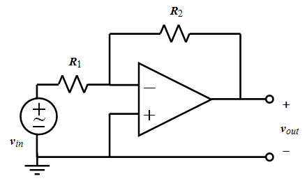
- Determine the gain of the op-amp in Figure 4 if R1= 20 kΩ and R2 = 200 kΩ. Repeat if R1 = 10 kΩ.
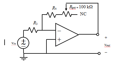
- In Figure 5, determine the value of R3and R4 to provide an overall gain that can vary between -2 and -10. Comment on whether the values for these resistors are unique.
- Upload your work to Canvas before the beginning of the lab.
In-Lab Activities 电子工程
Required Items:
- myDAQ
- Parts Kit
- Breadboard and wires
Prototyping Board and Troubleshooting Hints for All Experiments
- Do all wiring with the power off.
- Keep wiring and component leads as short as possible.
- Connect the power supply leads and 0.1 mF bypass capacitors to the op-amp first.
- Connect all ground leads at the myDAQ analog ground (AGND).
- Recheck wiring before applying power to the op-amp.
- Take all measurements referenced to AGND.
- If unwanted oscillations appear at the output and the circuit connections are correct:
- Connect additional 0.1-µF bypass capacitors.
- Shorten the leads of the wiring.
- Check the test instrument, signal generator, load, and power supply ground leads. They should come together at one point.
Note: Oscilloscope Measurement Limits 电子工程
Before taking measurements with any oscilloscope, it is important to ensure that the oscilloscope can handle the expected circuit voltage levels. Note that on the myDAQ, above the analog input terminals AI 0 and AI 1 (which are used as the inputs to the oscilloscope), there is a label stating “AI (±10 V).”
This indicates that the myDAQ oscilloscope can only handle input voltages in the range of -10 V to +10 V. However, in some circuits in this class (like some of the op-amp circuits in the new few labs), there may be voltage swings as high as ±15 V. These signals would not damage the myDAQ hardware, but they would saturate the oscilloscope and give incorrect measurements.
To avoid this problem, we will purposely keep the op-amp output voltages within the ±10 V oscilloscope measurement limits, except for in Lab 4 Experiment 1, which doesn’t use the oscilloscope. When using the myDAQ for other classes/projects, however, you need to remember this limitation.
- Experiment 1: Open-Loop Op-amp Saturation Characteristics
The purpose of this experiment is to investigate the open-loop characteristics of the LF412 op-amp, particularly the ± saturation voltages.
Procedure: 电子工程
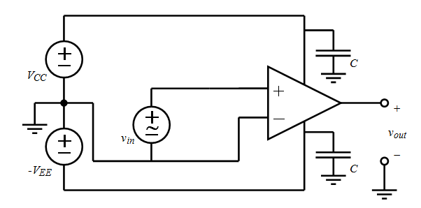
- Construct the network shown in Figure 2 using the prototyping board layout shown in Figure 3 as a guide. You should confirm that the schematic and layout correspond. Note that the wiring diagram in Figure 3 uses op-amp B on the LF412 IC — pin 5 for v+, pin 6 for v–, and pin 7 for vout.
- Connect pins 4 and 8 to the – and + power rails of the prototyping board.
- Add 0.1 mF bypass capacitors.
- Connect the inverting input to ground.
- Set up the myDAQ function generator to serve as vin, which should be a squarewave with a frequency of 0.5 Hz, amplitude of 2 Vpp, and dc offset of 0 V. This input will cause the output of the op-amp to alternate between positive and negative saturation. Note that this input is connected to the non-inverting terminal of the op-amp.
- Set up the myDAQ DMM to observe voutby connecting the DMM probes between vout and ground. The DMM should be on the DC voltage measurement – the first button.
- Once you have verified all your connections, connect the AGND connection to the ground, connect the +15V terminal to the + power rail, and connect the -15V terminal to the – power rail. Then, turn on the function generator output.
- Construct the network shown in Figure 2 using the prototyping board layout shown in Figure 3 as a guide. You should confirm that the schematic and layout correspond. Note that the wiring diagram in Figure 3 uses op-amp B on the LF412 IC — pin 5 for v+, pin 6 for v–, and pin 7 for vout.
Note: Do NOT connect +15V and -15V backward, as this will damage your op-amp, rendering it useless.

Figure 2. 电子工程
Network for studying the open-loop characteristics of an op-amp. The power supply voltages should be VCC = VEE = 15 V. The bypass capacitors should be 0.1-mF ceramic capacitors that are available in your EE 210 parts kit. The input voltage vin is to be provided by the myDAQ function generator, and the output voltage vout is to be observed on the myDAQ DMM.
Figure 3. Prototyping board layout for the network shown in Figure 2. Note 1: This diagram is using op-amp B on the LF 412. Note 2: The capacitors are shown as flat here. You should not bend them that way, however.
- Measure and record on your lab worksheet the op-amp’s positive and negative saturation voltages, designated as Vsatand -Vsat, by observing the op-amp output voltage on the DMM, which should switch back and forth between 2 voltage values every second (due to the 0.5 Hz signal frequency).
Note: You may not want to use the “Auto” mode on the voltmeter as this may yield inconsistent results. Instead, set the mode to “Specify Range”, and set the range to “20V”.
Q1 (answer on the lab worksheet): Compare your measured saturation voltages with the stated values on the LF412 datasheet. On the LF412 datasheet, saturation voltage is listed as output voltage swing, so examine the LF412 Datasheet and find the minimum and typical output voltage swing (when powered at +/- 15V). Write these values down on the worksheet and compare them with your measured values.
Experiment 2: Inverting Amplifier – Transfer Characteristic 电子工程
Now we will use the op-amp in closed-loop form, which is the normal mode of usage. The purpose of this experiment is to measure the transfer characteristic of an inverting amplifier. The transfer characteristic is a plot of output voltage vs. input voltage for a range of input voltage values. It can be found experimentally by measuring the output voltage amplitude for a variety of input voltages and plotting output voltage vs. input voltage. We will also investigate the current limits of the op-amp.
- Procedure:
- Construct an inverting amplifier circuit on your prototyping board as shown in Figure 4. Note that in this schematic and future schematics, the power connections for the op-amp are not shown; it is understood that they are necessary. Use R1= 20 kΩ and R2 = 200 kΩ. Measure and record on the worksheet the actual resistor values before putting them in the circuit.

- Set up the myDAQ function generator to serve as vin, which should be a sinusoid with a frequency of 100 Hz, amplitude of 0.25Vpp, and dc offset of 0 V. Note that this input is now connected, through resistor R1, to the inverting terminal of the op-amp.
- Set up the myDAQoscilloscope to observe vin on Channel 0 and vout on Channel 1. Observe that the output is an inverted and amplified version of the input signal.
- Save a screen capture image of the oscilloscope display and upload it into the worksheet.
To measure the transfer characteristics of the inverting op-amp 电子工程
Start increasing the amplitude of the input signal in 0.25 Vpp increments and record the input voltage amplitudes and corresponding output voltage amplitudes in the table on your worksheet. Make sure to include the sign inversion. You will notice that eventually, the oscilloscope display will saturate due to the ±10 V limits of the oscilloscope. Once this happens, stop taking measurements. Note: If an oscilloscope with a larger voltage range were used, the output saturation would
1.happen at a higher voltage and would be due to the op-amp saturating (see Experiment 1), rather than due to the oscilloscope’s limitations.
2.Create an output voltage vs. input voltage plot from your data in step 5. Calculate the slope of the plot, which represents amplifier gain, in this linear region and record the gain on your worksheet. Compare with the expected gain based on the nominal values of R1and R2 and with the expected gain based on the actual resistor values. Save a screen capture of this plot and upload it into the worksheet.
3.Turn off the function generator. 电子工程
Add a variable-resistance output load to your circuit by connecting a 270 Ω resistor in series with a 100 kΩ variable resistor (rheostat) between the output terminal and ground. A 100 kΩ variable resistor is realized using the wiper terminal (middle terminal) and one of the end terminals of a 100 kΩ potentiometer. Set the potentiometer for maximum resistance.
4.Now turn on the function generator and adjust the input amplitude so that the output signal has a voltage reading of 16 Vpp. The output signal should not be distorted at this point. Sweep the potentiometer wiper across its entire range and observe the shape of the output signal.
5.Save a screen capture image of the oscilloscope display for the minimum load resistance and upload it into the worksheet.
Q2 (answer on the lab worksheet): Explain, in words, what is causing this result to happen. From this activity, what conclusions can you make about the effect of the load resistance on the operation of the amplifier?
Experiment 3: Inverting Amplifier with Variable Gain 电子工程
The purpose of this experiment is to design an inverting amplifier with a variable gain. This can be done by introducing a variable resistor in the feedback path of a canonical inverting amplifier. In this application, the potentiometer is once again utilized as a variable resistor by using the wiper terminal (middle terminal) and one of the end terminals. The other end terminal is left open-circuit in this situation.
- Procedure:
- Construct the circuit in Figure 5 with the values of R3 andR4 determined in the prelab to provide an overall gain that can vary between –2 and –10. Note that due to the limited number of unique resistors in the parts kit, you will need to select resistors with values close to the calculated nominal values. This means that your actual min/max gains will not be exactly -2 and -10. Measure the actual values for R3, R4, and Rpot before inserting them into the circuit. Record these values on your lab worksheet.
- Set up the myDAQ function generator to serve as vin, which should be a sine wave with a frequency of 100 Hz, amplitude of 1 Vpp, and dc offset of 0 V.
- Set up the myDAQ oscilloscope to observe vinon Channel 0 and vout on Channel 1.
- Construct the circuit in Figure 5 with the values of R3 andR4 determined in the prelab to provide an overall gain that can vary between –2 and –10. Note that due to the limited number of unique resistors in the parts kit, you will need to select resistors with values close to the calculated nominal values. This means that your actual min/max gains will not be exactly -2 and -10. Measure the actual values for R3, R4, and Rpot before inserting them into the circuit. Record these values on your lab worksheet.


Figure 5.
Inverting amplifier with variable gain. NC (not connected) indicates that one end of the potentiometer is NOT connected.
- Vary the potentiometer between its minimum and maximum value and examine the output signal over this entire range. Using voltage amplitude measurements, determine and record the actual minimum and maximum gain on the worksheet. Also, calculate and record the expected minimum and maximum gains based on the nominal resistor values and actual resistor values.
- Q3 (answer on your lab worksheet): In this lab, a variable gain amplifier was constructed by adding a variable resistor in series with one of the existing fixed resistors in a canonical amplifier configuration. An alternate approach would be to replace one of the fixed resistors with a variable resistor.
- If the potentiometer were inserted in place of R4in Figure 5 (rather than in series with it), determine the resulting minimum and maximum gains based on nominal resistor values. Also, comment on the fundamental difference between the gain range in this proposed circuit vs. the gain range in the actual circuit that you built.
- What would happen if the variable resistor were inserted in place of R3in Figure 5, rather than its given location? What potential problems could occur?
Experiment 4: Non-Inverting Amplifier – Transfer Characteristic 电子工程
The purpose of this experiment is to observe and measure the transfer characteristic of a non-inverting amplifier.

Procedure:
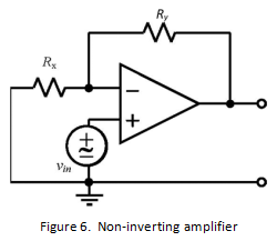
- Construct on your prototyping board the non-inverting amplifier as shown in Figure 6. Select RXand RY to provide a voltage gain of 10 V/V. Use a value for Rx ≥ 5 kΩ. Record the nominal and actual values for Rx and Ry on your lab worksheet.
- Repeat Experiment 2 steps 2-6, except vary the input voltage in 0.2 Vppincrements, starting a 0.2 Vpp. Enter all your data/plots on your lab worksheet.
- Save a screen capture for vin= 0.4Vpp and upload it into the worksheet.
更多其他:代写作业 数学代写 物理代写 生物学代写 程序编程代写 统计代写


