EE 210 Laboratory 05 Spring Semester
电子工程代写 This is the second of two laboratory sessions that provide an introduction to the op-amp. In this session, you will study three ···
This is the second of two laboratory sessions that provide an introduction to the op-amp. In this session, you will study three amplifiers designs: (1) the voltage follower/buffer, (2) an inverting summing amplifier, and (3) a voltage level display using the op-amp in comparator mode.
Pre-Lab Activities 电子工程代写
- Read the remainder of this handout.
- Read the laboratory supplement entitled “Light Emitting Diodes.”
- In Figure 3, first determine the values of R1, R2,and R3 so that:
- The gain Vout/Vleft= -2 (assuming that Vright is grounded)
- The gain Vout/Vright= -6 (assuming that Vleft is grounded).
Are these resistor values unique? For these resistor values chosen, compute the amplitude of Vout with:
- Vleftamplitude = 0 Vpp and Vright amplitude = 1 Vpp.
- Vleftamplitude = 1 Vpp and Vright amplitude = 0 Vpp.
- Both Vleftand Vright have amplitude = 1 Vpp
- Complete the analysis in steps 1-2 of Experiment 3.
- myDAQ
- Parts Kit
- Breadboard and wiresUpload your work to Canvas before the beginning of the lab.
In-Lab Activities 电子工程代写
00001Required Items:
- Experiment 1: Voltage Follower/Buffer – Loading Effect
The purpose of this experiment is to study how the buffer is used to overcome the loading effect for a practical source. In Lab 2, you studied the loading effect in the myDAQ +15V output. In this experiment, you will instead look at how a small load influences the output of a simulated practical source, and you will see how a buffer can be used to mitigate these effects.
All real signal sources (called “practical” as opposed to “ideal” sources) have internal resistances that cause the voltage at the terminal of the source to vary with respect to the current being drawn from the source. This phenomenon is known as the loading effect and is generally an undesirable effect that circuit designers need to deal with.
In circuit analysis, a practical source is modeled as an ideal voltage source in series with a small resistance (called a source resistance, Rs). Depending on the source being modeled, this source resistance can be < 1 Ω or as high as hundreds of ohms. The higher the source resistance, the more pronounced the loading effect becomes for the practical source.
In the myDAQ, the source resistance of the function generator is very small, so the loading effect is minimal and difficult to observe/measure. For the purposes of this lab, then, we will artificially increase the loading effect by placing a 330 Ω resistor in series with the function generator.
Procedure: 电子工程代写
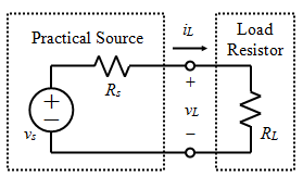
- Construct the circuit shown in Figure 1. Configure the Function Generator to generate a 100 Hz, 6 Vppsinusoid, with dc offset of 0V. Add a 330 Ω “source” resistance in series to create a practical source that will have an appreciable loading effect. Connect this “practical source” to a 10 kΩ load resistor. Finally, connect an oscilloscope to measure the voltage across the load resistor.
- Complete the analysis in steps 1-2 of Experiment 3.

Figure 1. Model of a practical source with a simple load. The practical source is the myDAQ Function Generator in series with an external 330 Ω resistor.
- Measure the voltage amplitude and find the current amplitude.
- Measure and record the value of the load resistor before inserting it into the protoboard.
- Measure and record the amplitude of vL.
- Calculate the corresponding amplitude of iLusing Ohm’s law.
- Repeat step 2 using the following load resistor values: 5.1 kΩ, 1.0 kΩ, and 510 Ω.
Q1 电子工程代写
(answer on the lab worksheet): Comment on how the output signal changes as you change the load resistor. And comment on how you would expect your results to be different if you didn’t add the external 330 Ω resistor. Speculate on what causes the result you observed.
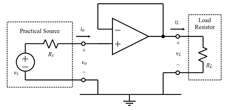
- Now construct the circuit as shown in Figure 2. using the same “practical source” (Function Generator + 330 Ω series source resistance) as before and using the 10 kΩ resistor as the load. Now, we have an op-amp buffer circuit (voltage follower) between the source and the load. Connect Channel 0 of the oscilloscope to measure vo(the input voltage) and connect Channel 1 of the oscilloscope to measure vL (the load voltage).

Figure 2. Op-amp voltage follower (buffer) circuit.
- Measure/calculate and record on your lab worksheet the amplitude of vLand iL for the remaining three load resistor values as before.
Q2 (answer on the lab worksheet): Comment on how the results have changed now by using the buffer circuit. Q3 (answer on the lab worksheet): When a voltage follower circuit is used, the current to drive the low-resistance load is not coming from the signal generator anymore — where is the load current coming from?
2.Try using a 68 Ω load resistor on the output of the buffer circuit. 电子工程代写
Take note of the waveform shapes for the input and output of the buffer circuit.When you measure the output with the 68 Ω resistor load in place. You should notice some output signal distortion, even with the buffer in place. This distortion can be due to one or both of the following limitations: 1) An op-amp can only output a certain amount of current before it begins behaving nonlinearly.
Every op-amp has a maximum positive current. Called “sourcing current”, that it can generate to drive a load. Likewise, there is also a maximum negative current, called “sinking current” that can flow into the output terminal of the op-amp; 2) In addition, the myDAQ itself has a maximum current that it can deliver to a circuit.
Q4 (answer on the lab worksheet): 电子工程代写
Look up the LF412 spec sheet and find nominal value(s) for this sourcing current limit. Based on this value and on the maximum voltage of the signal driving the op-amp. Determine the minimum load resistance that could be driven by the LF412 op-amp without hitting op-amp current saturation. Also, look up the myDAQ spec sheet and find the maximum output currents for the ± 15 V supplies.
Assuming that all this current is available to drive a load attached to the op-amp. Determine the minimum load resistance that could be driven by the LF412 op-amp without hitting myDAQ current saturation. Based on these two estimates, determine whether it is op-amp limitations or myDAQ limitations (or both) that lead to the degradation of the output signal when attaching the 68 Ω load resistor.
-
Experiment 2: Inverting Weighted Summing Amplifier
The purpose of this experiment is to design an inverting weighted summing amplifier. In this application, two voltage signals from two separate sources are amplified by different amounts and then added to each other. Resulting in a single signal at the output. An example of where this circuit is useful is for converting stereo audio signals to mono for playback through a single speaker. Another use of this type of circuit is to average signals together from multiple sensors to get a more accurate reading of whatever property you are measuring.
Procedure:
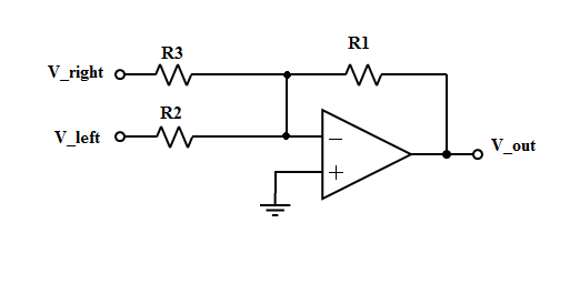
- Construct the circuit in Figure 3 using the values of R1, R2,and R3 as determined in the prelab. Measure and record the actual values of R1, R2, and R3 before inserting them into the circuit.

Figure 3. Inverting summing amplifier.
1.Since this is a linear circuit we can apply the property of superposition. 电子工程代写
1.This means that we can experimentally measure the output of the circuit for vrightwith vleft set to zero, and vleft with vright set to zero. The actual output will be the sum of the two responses.
-
- Set up the myDAQ function generator to serve as vright, which should be a sine wave with a frequency of 3250 Hz, amplitude of 1 Vpp, and dc offset of 0 V. Connect the function generator to the vrightinput terminal.
- Short circuit vleftto ground.
- Confirm that voutis as predicted in the prelab. This step is important to determine if your circuit is operating properly.
- Disconnect the function generator and open-circuit vleft.
- Set up the myDAQ function generator to serve as vleft,which should be a sine wave with a frequency of 440 Hz, amplitude of 1 Vpp, and dc offset of 0 V. Connect the function generator to the vleft input terminal.
- Short circuit vrightto ground.
- Confirm that voutis as predicted in the prelab. This step is important to determine if your circuit is operating properly.
- Disconnect the function generator and open-circuit vright.
2.To fully observe the summing capabilities of this circuit 电子工程代写
We need to be able to simultaneously create two distinct waveforms to drive the circuit. The myDAQ function generator can generate only one sinusoid at a time, so instead. We will use the “Arbitrary Waveform Generator” tool from the NI ELVISmx Instrument Launcher. Which allows us to generate two different waveforms simultaneously and send them to the AO 0 and AO 1 outputs. Specifically, our test signals will consist of a 440 Hz tone in the left channel and a 3520 Hz tone in the right channel (the nature of this test signal is similar to that used in stereo audio applications).
3.Create two distinct signals using the “Arbitrary Waveform Generator” tool as follows.
-
-
- Download the test files “1Vsine440.wdt” and “1vsine3250.wdt” from Canvas and save them somewhere convenient.
- Open the Arbitrary Waveform Generator tool.
-
- Click the folder icon for the AO 0 output channel, navigate to the test file “1Vsine440.wdt” and click “OK.” Repeat this with the AO 1 output channel and the file “1Vsine3250.wdt.”
-
Make sure the checkboxes enabling both output channels are checked. 电子工程代写
- Manually enter the Update Rate as 100,000 (this refers to the number of samples per second used to create the test files. Allowing the tool to recreate the signals properly).
- Connect the AO 0 output to the AI 0+ input and connect the AO1 output to the AI 1+ input. Make sure the AI 0- and AI 1- terminals are both connected to AGND.
- Run the Arbitrary Waveform Generator tool and use the Oscilloscope tool to verify that a 440 Hz signal is coming from the left channel (Channel 0). And that a 3250 Hz signal is coming from the right channel (Channel 1).
- Save a screen capture image of the oscilloscope display, and upload it into the worksheet.
- Now we will drive the circuit simultaneously with the two test inputs we created in step 3. And observe the mono output signal, which will be an amplified sum of the two test inputs. Disconnect the inputs from the oscilloscope and instead connect the Left and Right channels (AO 0 and AO 1) to vleftand vright, respectively, in your circuit.
-
Set up your oscilloscope to monitor vouton Channel 1. Play the test file. 电子工程代写
- Save a screen capture image of the oscilloscope display, and upload it into the worksheet.
-
- Swap the right and left channel connections in your circuit and repeat step 4.
Q5 (answer on the lab worksheet): Imagine that you are using the circuit in Figure 3 to convert a stereo audio signal (2 channels) to a mono audio signal (1 channel). Due to a defect in your audio player. The left channel amplitude is only 0.2 Vpp. However, the right channel amplitude is 4 Vpp. How would you modify the circuit in Figure 3 to compensate for this defect so that both the left. And right channels contribute equally to the mono output and so that the amplitude of the output signal is 20 Vpp? Show all calculations. And draw the modified circuit, and upload your design into your lab worksheet.
-
Experiment 3: Voltage Level Display 电子工程代写
The purpose of this experiment is to use op-amps in comparator mode. Along with light-emitting diodes (LEDs), to create a simple voltage level meter. As seen in Lab 04 Experiment 1, when an op-amp is employed without negative feedback. Its output saturates to the positive or negative voltage rail depending on whether the voltage level at the inverting input or the non-inverting input is greater. (Comparators “compare” the voltage level at each of the inputs!).
In this experiment, we’ll use comparators to compare a voltage signal with a series of reference voltages and use the output of the comparators to light a string of LEDs. Specifically, we will design a simple 2-level voltage level display that will light one LED when the input signal reaches 4 V and light a second LED when the input reaches 8 V.
Procedure: 电子工程代写
- When we build our level meter, we will need some fixed voltages to serve as references for comparison. We can produce these voltage references through the use of voltage division — dividing down the positive voltage rail used to power the op-amps. See Figure 4. Use your results from prelab to choose values for R1, R2, and R3 such that V1= 8 V and V2 = 4 V.

Figure 4. Voltage references for the level meter.
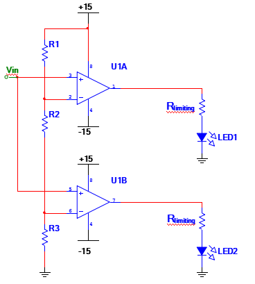
- Using your results in step 1, design and build the 2-level voltage level meter in Figure 5. Note that voltage node V1 in the voltage divider (Figure 4) is connected to the inverting input of one of the op-amps and voltage node V2 in the voltage divider is connected to the inverting input of the other op-amp. Use the equation in the “Light Emitting Diodes” supplement to determine values for Rlimiting so that the current through each LED (when on) is 10 mA, as specified in the supplement.

Figure 5. Two LED level meters.
- With the circuit powered, but without applying any input signal, measure the voltage level at the invertinginput of each of the comparators and record these values on the lab worksheet and verify that these actual reference voltages are close to the desired references from step 1.
- Supply a voltage at Vin using the myDAQ DC Level tool. Start at 0V and increase the DC voltage slowly until the first LED comes on. Measure this input signal voltage and record the value on the lab worksheet. Continue to increase the voltage until the second LED comes on. Measure the signal voltage again and record the value on the worksheet. Compare the operation of this voltage level display with the desired operation.
- Now, replace the DC Level tool with the Function Generator, and change Vinto a 440 Hz sinusoid with an amplitude of 1V (2 Vpp) and no DC offset. This is a reasonable mathematical model of a typical voice/music signal. Slowly increase the amplitude of this sinusoid and observe what happens to the LEDs as the input signal’s amplitude reaches the 4 V (8 Vpp) threshold. Next, slowly increase the DC offset and observe what happens as the offset reaches 4 V.
Q6 (answer on the lab worksheet): 电子工程代写
In step 3.5, when the LEDs are “on”, do they appear to be steady or blinking? Are they actually steady or not? Explain. To verify your conjecture, decrease the frequency of the sinusoid to 10 Hz and observe the LEDs.
Q7 (answer on the lab worksheet): Using the circuit in this experiment as a guide, design a 4-level LED voltage meter. The LEDs should come on sequentially when Vin = 2 V, 4 V, 6 V and 8 V respectively. Include a fully labeled schematic and all analytical derivations. Upload your work into the worksheet as a scanned PDF.
更多其他:代写作业 数学代写 物理代写 生物学代写 程序编程代写 统计代写


