EEEE2046 – Practical Engineering Design Solutions and Project Development
Electronics Project – Filter Design Coursework
电子项目代写 The band-pass filter design you have used in your hardware design is a simple design and does not have very good performance…
Background
The band-pass filter design you have used in your hardware design is a simple design and does not have very good performance (as you have hopefully already noticed!). It is usually straightforward to produce a filter with a given -3 dB cut-off point, but this is not the only parameter that you need to consider when designing a filter.
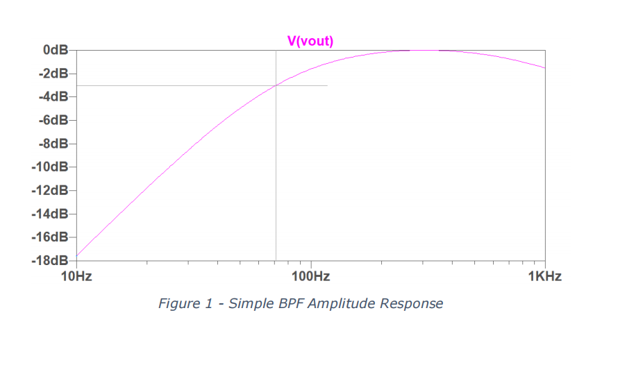
Figure 1 shows the low frequency amplitude response for a filter similar in design to yours. The rate at which the signal is attenuated (called the roll off) beneath the -3 dB cutoff (indicated by the dark grey lines) is 20 dB/decade; in other words when the frequency is reduced by a factor of 10, the attenuation increases by 20 dB. This is because the design is a first order filter.
There are two things that are inadequate about this filter response: 电子项目代写
- There is still a reasonable amount of attenuation occurring in the range of frequencies we are interested in – the amplitude response in our pass band is not very flat. Only in the region of around 250 Hz to 400 Hz is there substantially lower than 1 dB attenuation.
- Because the filter has a slow roll off, signals at low frequencies can still make a noticeable contribution to our result. At 10 Hz in this example, the input has been attenuated by 18 dB, or 0.126 of the original signal level. In the context of the Doppler radar design, people walking nearby or small movements caused by holding the radar unit could potentially interfere with our current filter design.
The aim of this individual coursework is to design a higher order filter that can better attenuate the low frequency components, i.e. a high pass filter.
Learning outcomes:
1- Enhance the level of understanding in filter design specifically higher order filter.
2- Appreciate issues in designing filter using different approaches
3- Improve learner skills in designing course work document.
Submission 电子项目代写
You will submit your coursework via Moodle in two parts:
- A written document that contains calculations for your filter design and the other written components asked for.
- A zip file containing the LT Spice schematic files for your designs.
See the Moodle submission link for the deadline. Please do not leave your submission to the last minute, even one second late will incur the normal penalty, plenty of time has been allocated to this coursework so that you can plan your own time management. If you experience technical problems with submission, you should take screen-grabs and submit an extenuating circumstances form, however these are generally not accepted as a reason for late submission when you have had many weeks to complete the work.
These coursework sheets contain a miniature tutorial on filter design with instructions which you should document in your report. There are also a list of references at the end of the document that should be used to get full understanding of the topic.
Page limit: Absolute maximum of 10 pages (including all tables, charts, references etc.). However, I would expect most submissions to be well under this due to use of appropriate images instead of text.
Report structure: 电子项目代写
You should include a short introduction stating the aims of the work. Then for each task, document your method, include results and analysis, answering questions which are posed in this document. At the end of your report, you should include a short paragraph as a conclusion on if the aims of the work were achieved. A references section in IEEE format should be included at the end of your report (where appropriate). You should include the following sections in your report. 1- Introduction (task1), 2- Results (tasks 2,3), 3- Discussion, 4-Conclusion, 5- References, 6- Appendix (optional).
Tasks
Task 1
Carry out research into different filter characteristics and their applications. In your report, provide a description of the advantages and disadvantages of each of Butterworth, Chebyshev and Bessel filter designs and include examples of where these filters can be found in real life products. You can then expand and explain on why, for that particular application, it is beneficial to have such a filter. It’s recommended to use IEEE publications, IET, books and scientific websites. Wikipedia can’t be used in your reference list.
Task 2 电子项目代写
Design and simulate a high pass Butterworth filter using the Sallen Key topology, to meet the following specification:
Gain: 1
Pass band: 100+(use your student ID/ last 2 digits)Hz
Stop band: 50Hz
Stop band attenuation: 30dB
Further details of how to go about the technical aspects of this task are included later in this document – this section just aims to describe what you need to do.
You should include in your report a complete set of the calculations for your design, with appropriate explanations. Any circuit submission without an accompanying set of working out will not be marked.
Once you have your complete set of calculations and component values, you should implement your design in LT Spice, using exact rather than rounded component values – e.g. use 141.2pF if that is what your calculation suggested, rather than rounding to 140pF. For the op-amp, use the LT1498. To simplify your design, please make use of a dual rail power supply, i.e. ±5V, and centre all of your signals on ground.
You should include an image of your schematic design in your report.
To verify your design, carry out two simulations:
-
An AC simulation to determine the amplitude response of your circuit. 电子项目代写
Use an AC 1 V input and plot the output of your complete design. Check the -3 dB low cut off frequency of your filter from the plot (ensure you have used enough points in the AC sweep to obtain a smooth response). If it does not match, check your design and calculations. Include a figure containing the plot of the amplitude response in your report, and also include the -3dB low cut off frequency achieved.
-
A transient response simulation.
You should configure your input voltage source to be 1 V amplitude with an appropriate frequency. Check the operation of your circuit well into the pass band, e.g. at 500 Hz. Please choose an appropriate simulation length so that around 10 cycles of the input can be seen. Include a copy of the plot in your report then describe what you expect the output to be and whether the circuit output matches this. Repeat the transient simulation with an input at 10Hz. You should determine what you expect the output voltage to be at this frequency, include your output plot and state whether it meets your expected value.
What is the high cut off frequency of your circuit? What causes this limit? Provide an answer to these questions in your report.
Task 3 电子项目代写
Once you are happy with the operation of your circuit, you will consider practical implications of building the circuit. Create a new copy of your design that uses resistor and capacitor values that are readily available. Resistor and capacitor values are typically available in so-called “E” ranges. There is a link in the references section that provides more details. You are permitted to use component values from the E24 range only, and should only use a single resistor/capacitor in each place. This means that for the capacitor with value 141.2 pF already used as an example, there would be a choice between a 130 pF and 150 pF capacitor. Using a combination of 130 pF + 10 pF would not be accepted.
Include an image of your new design in your report, and include both exact component value and E24 component value schematic files in your zip upload.
Simulate the new design with an AC simulation in the same way as the previous circuit. Include a copy of the amplitude response in the report. What is the new -3 dB low cut off frequency?
Provide a description of how component tolerance, typically 5% for resistors and 10% for capacitors, will affect the performance of your design.
Finally, describe how your circuit would have to be modified if the specification was changed to include amplification within the pass band. Include a circuit diagram to illustrate this.
Academic Misconduct – Plagiarism and Collusion 电子项目代写
This coursework is an individual piece of work and you should be careful about how you work. You may discuss concepts with other students, however you should not complete the work together and submit identical reports.
You are strongly advised to read the University Quality Manual section on Academic Misconduct, in particular the sections on Plagiarism and Collusion:
https://www.nottingham.ac.uk/academicservices/qualitymanual/assessmentandawards/academic-misconduct.aspx
If after reading the Quality Manual you are uncertain about academic misconduct, speak with your personal tutor.
Filter Notes
There are many good books on active filter design available in the library, they are well worth a read. You should already be familiar with much of this work from the notes on filters from In EEEE2044, We will be discussing filters in more detail and provide you with a (with Dr Woolfson), please refer to those notes and example sheets for hints with these tasks. There are also many application notes on filter designs on the internet.
The notes below contain a brief summary of the some of the aspects of filter design that you may find useful. You should, however, always expect to have to do your own research in order to be able to complete coursework tasks. 电子项目代写
We have already seen that the 1st order BPF you produced for the lab work is not adequate for this coursework task. To meet that specification, a higher order filter is required. Figure 2 shows a set of Butterworth filter responses for different orders of design. The black response shows the ideal “brick wall” response, where all signals beneath the cut off frequency are completely attenuated and all frequencies above the cut off are passed perfectly. You can see that as the filter order increases, the response of our real filter more closely approximates the ideal response, both above and below the cut off frequency.
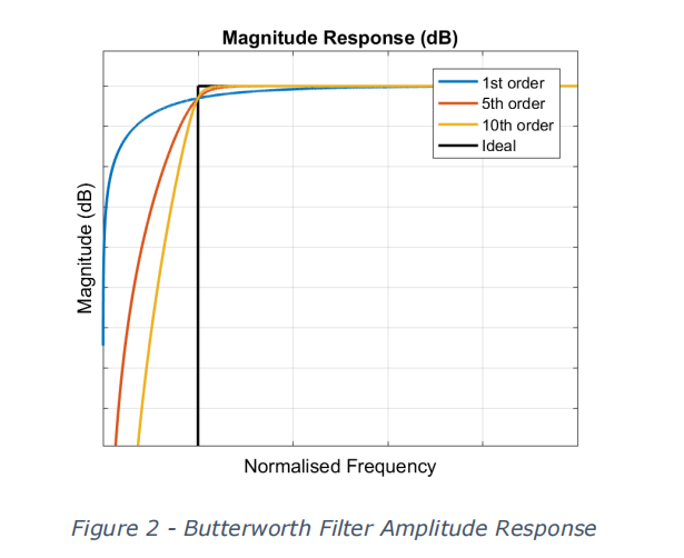
What this shows, is that there is a direct relationship that links the pass frequency, the stop band frequency, the stop band attenuation and the order of the filter. What this tells you is that given your specification, the first thing you need to do is determine the order of filter that can meet that specification.
The transfer function of an Nth order high pass Butterworth filter is given as:

Where ? = 2??, ?? is the pass band frequency and ? is the maximum gain in the pass band (Amax)1 . For the unity gain filter that you are designing, set this to 1. By manipulating formula 1 and using the known values of the pass band frequency, the stop band frequency and the response of the filter at the stop band frequency it is possible for you to calculate the order of filter required.
A more general way of looking at the frequency response of a unity gain high pass filter is shown in equation (2).

Where ?? is the corner frequency between the pass band and stop band and ? is the quality factor of the filter. This can be used to help when designing for a particular filter topology.
Any given filter response (Butterworth, Chebyshev, Bessel or one of many others) can be implemented in a variety of ways. In this coursework we are using the Sallen Key topology, but you should also be already familiar with multiple feedback topology and maybe some others.
Figure 3 shows a form of a unity gain, second order Sallen Key filter (In this situation the output of the op-amp is fed back to the input, so K = 1 in equation 3 and one of the terms in the denominator vanishes). The circuit contains two capacitors and two resistors. The generalised Z impedances are replaced with resistors or capacitors in different arrangements to produce different circuit behaviour. You will need to find the appropriate arrangement for a high pass filter.
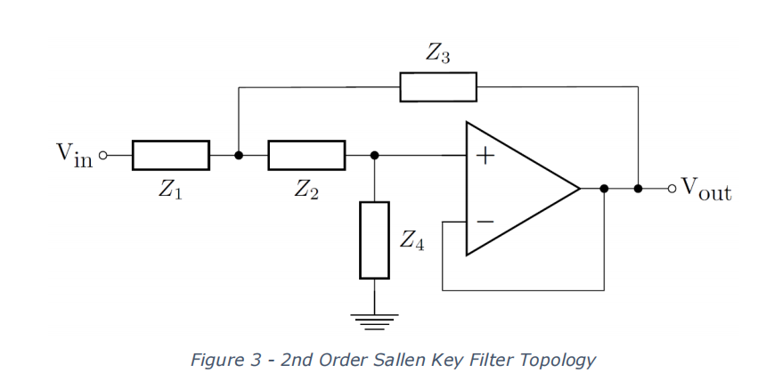
The transfer function of a second order high pass Sallen Key filter is given in Equation (3).

Where ? is the gain in the pass band. Setting ? = 1 and with some simple manipulation, Equation (4) is obtained.
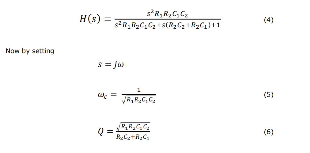
Then Equation (4) becomes the same form as the general second order filter Equation (2). In other words, we have the equations for a Sallen Key specific implementation of a unity gain second order high pass filter. Using equations (5) and (6) with known values of ?? and ? allows you to calculate the values of resistors and capacitors required. You will also need to follow the principles on component selection discussed earlier in this document.
Table 1 contains a list of polynomials for different order Butterworth filter designs. Each quadratic equation represents a second order filter stage, and is equivalent to the denominator of Equation (2). In other words, this table gives the numerical values to use for Q.
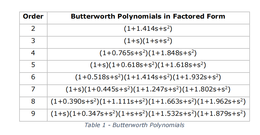
It can be seen from Table 1 that higher order filters can be created from multiple stages of 2nd. And 1 st order filter circuits, with different component values in each stage to produce the desired response. Hence once the principles of designing a single 2nd order stage are understood. It is trivial to apply this understanding to the design of higher order filters.
References and for more information 电子项目代写
“Standard Series Values in a Decade for Resistances and Capacitances”,
https://www.vishay.com/docs/28372/e-series.pdf
“Microelectronic circuits”, various editions, Adel S. Sedra, Kenneth C. Smith and other books in
the library under a similar index number.
“Active Low Pass Filter Design”, TI Application Note sloa049b.pdf
“Butterworth Filter Design” https://www.electronics-tutorials.ws/filter/filter_8.html
All documents as suggested in the Filter components of H62EPC.


