Introduction
Arithmetic Logical代写 Top module is for receiving the input signal of 10 switches and two buttons. The lowest 8 bits represent the input data.
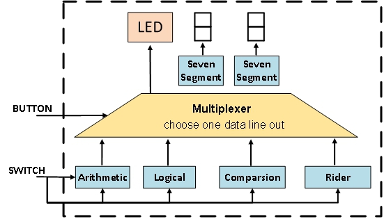
The Top module is for receiving the input signal of 10 switches and two buttons. The lowest 8 bits represent the input data. The highest 2 bits are used for controlling the Top module to process the input data. The button is for setting the work mode of the TOP module. The output data is shown in LED and Segment Displays.
The system is shown in figure 1, and it includes five sub-modules: Arithmetic, Logical, Comparison, Multiplexer, and SevenSegment. Arithmetic, Logical, Comparison process the input data according to the opt signal and send the result of the binary format to Multiplexer. The multiplexer receives the data and output the data into Segment Displays or display, which choose the output according to the button. SevenSegment is in the, and it is used for decoding the data. Then, the decoding data can be shown in Segment Displays. For example, the input is 0x1010, and the decoding data is shown as A in the Segment Displays.
Block diagram Arithmetic Logical代写

Figure 1.
Truth table Arithmetic Logical代写
| Switch1 | Switch0 | Arithmetic | Logical |
| 0 | 0 | Add | AND |
| 0 | 1 | Subtract | OR |
| 1 | 0 | Multiply-by-2 | XOR |
| 1 | 1 | Divide-by-2 | NOT |
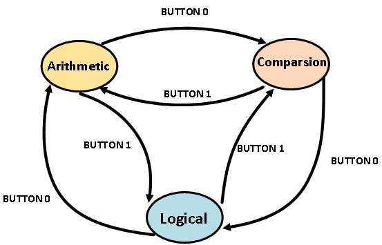
Figure 2 shows the conversion among different modes and the default mode is Arithmetic.

Figure2. Conversion among different modes.
Result Arithmetic Logical代写
Button0 and button1 are used for changing the work mode of CPU. Every time we press the button0, the work mode is switched in a clockwise direction as shown in figure2. Similarly, every time we press the button1, the work mode is changed in the counterclockwise direction as shown in figure2.
The 8th and 9th bit of the switch signal is to choose the mode of CPU as shown in the truth table. The 4th bit, 5th bit, 6th bit, and 7th bit of switch is used for the input of data X while the 3rd bit, 2nd bit, 1st bit, and 0th bit is used for the input of data Y.
When the system is working on comparison mode, G, E, and L signal is connected to LED9, LED8, and LED7, respectively. If the LED9 is on, the data X is larger than data Y. If the LED8 is on, the data X is equal to data Y. If the LED7 is on, the data X is smaller than data Y. When the system is working on another mode, The LED9 represents the carry of SUB and ADD. The other LED bit represents the output data in binary format.
Picture
The simulation result is shown in Figure 3. According to Figure3, the working mode is Arithmetic in the initial time. Besides, the working mode is Comparison mode and Logical mode in the final two rising edges of the clock, respectively. The system output all of the results and the opt signal does not affect the system when the system is working on the comparison mode.
The button triggers the whole time of the simulation shown in figure 3 and the incident. For evaluate the function of the project, the function is tested in the order: 1. ADD (without output) 2.SUB 3.MUL 4.DIV 5.ADD 6~10.COMPARE 11.AND 12.OR 13. XOR 14.NOT 15. AND. All of the function is implemented according to figure 3.

Figure 3
Conclusion Arithmetic Logical代写
The ADD sub-module and Subtract sub-module is the hardest part of the project and most time is consumed in this part. Because the demand for this part is the most complex in the system, after implementing the project, I learned a lot in Verilog.
According to the behavior simulation, the system works in the right mode, and the output data is also correct.
In the future, we will implement the Magic module in the project and makes the project better than that in this time.

更多其他:Essay代写 数据分析代写 润色修改 Proposal代写 Capstone Projects Case study代写 心理学论文代写 哲学论文代写 计算机论文代写


您必须登录才能发表评论。