EE 210 Laboratory
Electronic engineering This laboratory session serves as an introduction to voltage division, potentiometers, and understanding···
This laboratory session serves as an introduction to voltage division, potentiometers, and understanding loading effects on the power supply.
Pre-Lab Activities Electronic engineering
- Read the laboratory supplement entitled “Potentiometer.”
- Read the remainder of this handout.
- Select appropriate resistor values R1and R2 in Step 6 of Experiment 1 to get the desired voltage swing. Assume the value of the potentiometer shown in Figure 3 is a 100 kΩ potentiometer. Comment on whether your resistor choices are unique values.
- Upload your work to Canvas before the beginning of the lab.
In-Lab Activities Electronic engineering
Required Items:
- myDAQ
- Parts Kit
- Breadboard and wires
Experiment 1: The Potentiometer and Voltage Division
The purpose of this experiment is to familiarize you with the potentiometer and then use the potentiometer to perform voltage division.
Procedure: Electronic engineering
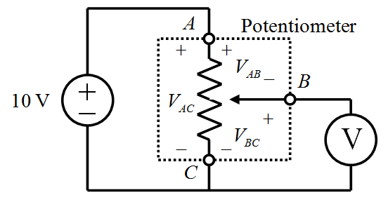
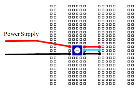
- Construct the network shown in Figure 1 using the prototyping board layout shown in Figure 2 as a guide.
Insert the 100 kΩ potentiometer into the prototyping board. Note that 11 equispaced tick marks surround the wiper of the potentiometer. Each tick mark represents a 10% increment in the location of the wiper.
Add the three parallel wires to the right of the potentiometer to provide easy access to terminal A, terminal B, and terminal C.
Before connecting the power supply, use the myDAQ DMM in ohmmeter mode to measure the resistance of the potentiometer between terminals A-C, A-B, and B-C. Investigate how these resistances change (or don’t change) as the wiper pin is rotated. Record your observations on your worksheet. Make sure to record the resistance between terminals A-C, as this information will be needed later.
When finished with your resistance measurements, set up the myDAQ AO 0 analog output to serve as the 10-volt source, using the DC Level tool from the NI ELVISmx Instrument Launcher. Refer to lab 1 for help with setting up the output.

Figure 1. Schematic of a potentiometer Electronic engineering

Figure 2. Prototyping board layout for the network shown in Figure 1.
- Set up the DMM as a dc voltmeter.
- Turn the wiper of the potentiometer counterclockwise as far as it will go using a screwdriver or “tweak tool”. This position will be 0%.
- Measure and record on the worksheet the angular position, VAC, VAB, and VBCat each 10% increment:
- Measure the value of VACusing the myDAQ DMM.
- Measure VABand then VBC using the myDAQ DMM.
- Turn the wiper of the potentiometer to the next tick mark.
- Repeat these steps until the wiper of the potentiometer cannot be turned any further (full scale – 100%).
- Construct two separate plots using MATLAB, Excel, or any plotting tool of your choice. Plot VAB position and VBC vs. position. Be sure to include appropriate plot titles, axis labels, and units. Save screen capture images of each plot and upload them as images into the worksheet.
-
In the configuration in Figure 1 Electronic engineering
- you should have observed that the voltage at terminal B of the potentiometer (VBC) can be set to any value between 0 V and 10 V. We now want to modify this circuit so that the voltage at terminal B of the potentiometer will range between 3 V and 7 V (using the same 10 V supply). This is done by adding appropriate fixed resistors in series between terminal A and the power supply and in series between terminal C and ground (see Figure 3). In the prelab, you used your knowledge of voltage division and the overall potentiometer resistance to determine appropriate values for R1and R2. Verify your design by building the modified circuit. Measure the minimum and maximum voltage at terminal B of the potentiometer and record these values on your worksheet.
Note: Not every resistor value is typically available from distributors. Electronic engineering
Due to the finite number of resistors in your parts kit, you may need to either connect multiple resistors in series to achieve the desired value or simply select a resistor that is close in nominal value to the desired resistor. This may slightly alter the maximum and minimum voltages that you measure at terminal B.

Figure 3. Schematic of a potentiometer as a variable voltage divider.
Q1 (answer on your worksheet): For the potentiometer circuit in Experiment #1 step 6 (Figure 3), calculate how the output voltage range would change if a 20 kΩ load is connected between point B and ground in parallel with the voltmeter. Note that the presence of a resistive load alters the voltage ranges of the potentiometer circuit. This is called the loading effect and will be examined in the next experiment. Based on this calculation, do you expect a load resistor to have more effect on the voltage swing if its resistance is low or high?
- Verify your answer to Q1 by connecting a 20 kΩ load resistor between terminal B and ground and measuring the minimum and maximum voltage at terminal B of the potentiometer. Record these values on your worksheet and compare it with your calculations for Q1.

Experiment 2: Characterizing a Practical Voltage Source and Understanding Loading Effects Electronic engineering
The purpose of this experiment is to study the loading effect on the myDAQ power supply. The loading effect is an undesirable side-effect of all practical (as opposed to theoretical) voltage sources (batteries, power supplies, function generators, etc.) in which the actual voltage across the external terminals of the source is less than the stated voltage whenever a current-drawing load is connected to the source. The loading effect is especially noticeable when the load has a low resistance. And large currents are being drawn from the source.
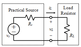
The loading effect occurs because all practical sources have an internal resistance that experiences a voltage drop when current is drawn from the source. These practical sources can be modeled, as shown in Figure 4, as an ideal voltage source vs. And an internal series resistor Rs, called a source resistance. This model of a practical source is called a Thevenin equivalent circuit and will be discussed during the lecture.
From basic circuit analysis, the terminal voltage of the function generator, vL, is given by:
From Figure 4 and the equation above, we see that as the load resistance RL decreases, the source current iL increases, the voltage drop across RS also increases, and the voltage VL that appears at the terminals of the function generator decreases.
In this exercise, you will experimentally determine the value of the internal source resistance Rs of the +15 volt power supply by measuring vL and calculating iL for a variety of load resistances and using your data to determine RS. In a later lab, you will learn how to use an op-amp buffer circuit to mitigate this loading effect.
Procedure: Electronic engineering
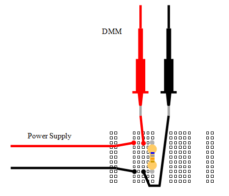
- Construct the network shown in Figure 4 using the prototyping board layout shown in Figure 5 as a guide. Note that the +15 volt output represents the practical voltage source to be characterized and that vLis to be observed using the myDAQ voltmeter. Use terminals +15V and AGND for the voltage source and use the DMM probes to measure the voltage across the load resistor.
Figure 4. A simple circuit for characterizing the loading effect on a practical source.

Figure 5. Prototyping board layout for the network shown in Figure 4.
Resistor color code in the image is just an example – it isn’t necessarily correct.
- For now, select a load resistor value of 75 kΩ; as always, you should measure and record the actual value before inserting it into the board.
- Measure and record (on your worksheet) the voltage vLfor the following values of load resistor: 75 kΩ, 5.6 kΩ, 1.2 kΩ, and 330 Ω.
- Measure and record the value of each load resistor before inserting it into the prototyping board.
- Measure and record the value of vL.
-
Calculate the corresponding current iLusing Ohm’s law. (Use the measured value for resistance.)
- From your data in Step 3 ,you should notice that the power supply’s terminal voltage (which is the same as the load voltage) drops as the load resistance drops, even though the supply’s nominal voltage is not being changed. This is commonly called a loading effect and is due to the internal resistance Rsof the voltage source.
- Using your data from step 3, construct a plot of the voltage-current characteristics of the power supply by plotting vL(vertical axis) vs. iL (horizontal axis). As always, include an appropriate title, axis labels, units, and upload a screen capture of the plot into the worksheet.
- Use your data from Step 3 and plot from Step 5 to estimate the value of the source resistance Rs. Because , the slope of the V-I plot is the negative of the internal source resistance, Rs.
Q2 (answer on your worksheet): Explain the significance of the loading effect and source resistance when designing and building a circuit with a low-resistance load.
更多其他:代写作业 数学代写 物理代写 生物学代写 程序编程代写 统计代写


