ATTEMPT ALL PARTS
EQUATIONS AND DATA TABLES ARE ATTACHED TO THE BACK OF
THE EXAM SCRIPT
物理作业代写 The numbers in square brackets in the right-hand margin indicate the marks allotted to the part of the question against which the…
The numbers in square brackets in the right-hand margin indicate the marks allotted to the part of the question against which the mark is shown. These marks are for guidance only.
An electronic calculator may be used provided that it does not have a facility for either textual storage or display, or for graphical display.
Q 1) 物理作业代写
a) From first principles for actuator disc theory show that the slipstream factor b is exactly twice the inflow factor a. Your answer should include appropriate sketches.[10]
b) A propeller driven aircraft has cruise speed 90ms−1 at an altitude where the air density is ρ = 1.1kgm−3. The thrust requirement is for a drag of 2.5kN. The chosen propeller operates with thrust coefficient CT = 0.09 at efficiency η = 0.86, advance ratio J=1.4.
(i) Calculate the actual propeller power requirement P˙ and required diameter D, (ii) Evaluate the inflow factor a.[5]
c) (i) Sketch and label a clear diagram of a blade element for a propeller. Your sketch must include geometric and aerodynamic angles, velocities and forces. Write down expressions for the blade element thrust and torque in terms of the blade element lift, drag and any other relevant parameter. (ii) Show that the blade element thrust is zero when

(iii) For inflow factor a=0.02, advance ratio J=1.5, at what non-dimensional spanwise location x does the blade element thrust become zero for![]() =1?[15]
=1?[15]
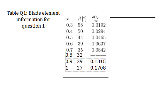
d) Perform a blade element theory calculation for the following propeller: number of blades B=2, uniform chord c=0.2m, J=1.31, D=2.7m, n = 25revs−1. The blade aerofoil section has Cl = 2πα, where α is the angle of attack in radians, and drag coefficient Cd =0.01, and the in-flow factor is estimated to be a = 0.02. Table Q1 shows the pitch angle β distribution. Non-dimensional thrust coefficient gradient ![]() at all the radial locations except x = 0.8 are shown along the entire blade.
at all the radial locations except x = 0.8 are shown along the entire blade.
Evaluate the non-dimensional thrust gradient ![]() 8, and calculate the propeller thrust coefficient.[20]
8, and calculate the propeller thrust coefficient.[20]
Q 2) 物理作业代写
a) Calculate the stagnation pressure ratio of a normal shock intake for flight Mach number M = 2.5 (equations for the normal shock process are provided at the back of the script, and use γ= 1.4). Is the value for this flight Mach number acceptable?[10]
b) (i) Describe and explain the operation of an axial flow turbine for a gas turbine engine. Sketch appropriate diagrams, and describe the functions of the major components and their inter-relationships.
(ii) Using equations in the data sheet, show that for the axial flow impulse turbinethe work w per unit mass flow is given by the expression
w = 2U(Ca tanα2 − U),
where the symbols have their usual meaning.
(iii) An impulse turbine blade pair operates with rotational speed 4000rpm, axialgas velocity Ca = 300ms−1, and the engine diameter at mid-blade height is 1.2m. The stagnation temperature drop is to be 130K. What is the required rotor entry gas angle α2?[25]
c) (i) Starting with the expression for the mass flow rate ˙m for a compressible, 1-D flow of velocity u through a duct of area A, ˙m = ρuA, where ρ is the gas density, show that an expression for the rate of change of duct cross-sectional area with gas velocity for isentropic flow is given by

where M is the local gas Mach number.
A turbojet nozzle assembly consists of a constant area afterburner duct followed by a choked, variable geometry nozzle.
(ii) Starting with the expression for mass flow parameter![]() ˙, show that the ratio of nozzle throat area with and without reheat is given by
˙, show that the ratio of nozzle throat area with and without reheat is given by ![]() .
.
(iii) In a particular condition gas flows into the afterburner duct with stagnationpressure and stagnation temperature of 0.75bar and 550K respectively. With afterburner lit the nozzle entry stagnation pressure and temperature are 0.705bar and 659K. Determine the increase of nozzle throat area when the afterburner is lit.[15]
For this question you should use γ = 1.4, R = 0.287kJkg−1K−1, Cp = 1.004kJkg−1K−1.
EQUATIONS AND TABULATED DATA 物理作业代写
QUESTION 1, tabulated data and blade element theory:
You may use the expression

for the thrust coefficient gradient for blade element theory.
Table Q1: Blade element information for question 1

QUESTION 2, normal shock relations: 物理作业代写

QUESTION 2, axial flow turbine blade pair:
Work per unit mass w = U(Cw2 − Cw3), degree of reaction Λ = 1 ![]() .
.
End of question paper


